I/O Device Driver
At this point, you have thoroughly studied the kernel (i.e., code under the grass directory of egos-2000), which is the most important component of an operating system. You have also studied cpu_intr.c and cpu_mmu.c under the earth directory holding the code for interrupts and virtual memory (i.e., CPU support in addition to user-level ISA that is critical to implementing the kernel).
In this project, you will further read earth/dev_disk.c and earth/dev_tty.c. The first file contains the driver for an SD card and the second file contains the driver for a terminal (i.e., keyboard input and screen output). While the 2 files combined have fewer than 200 lines of code, they are great examples of memory-mapped I/O, an important concept to learn.
I/O device and serial bus
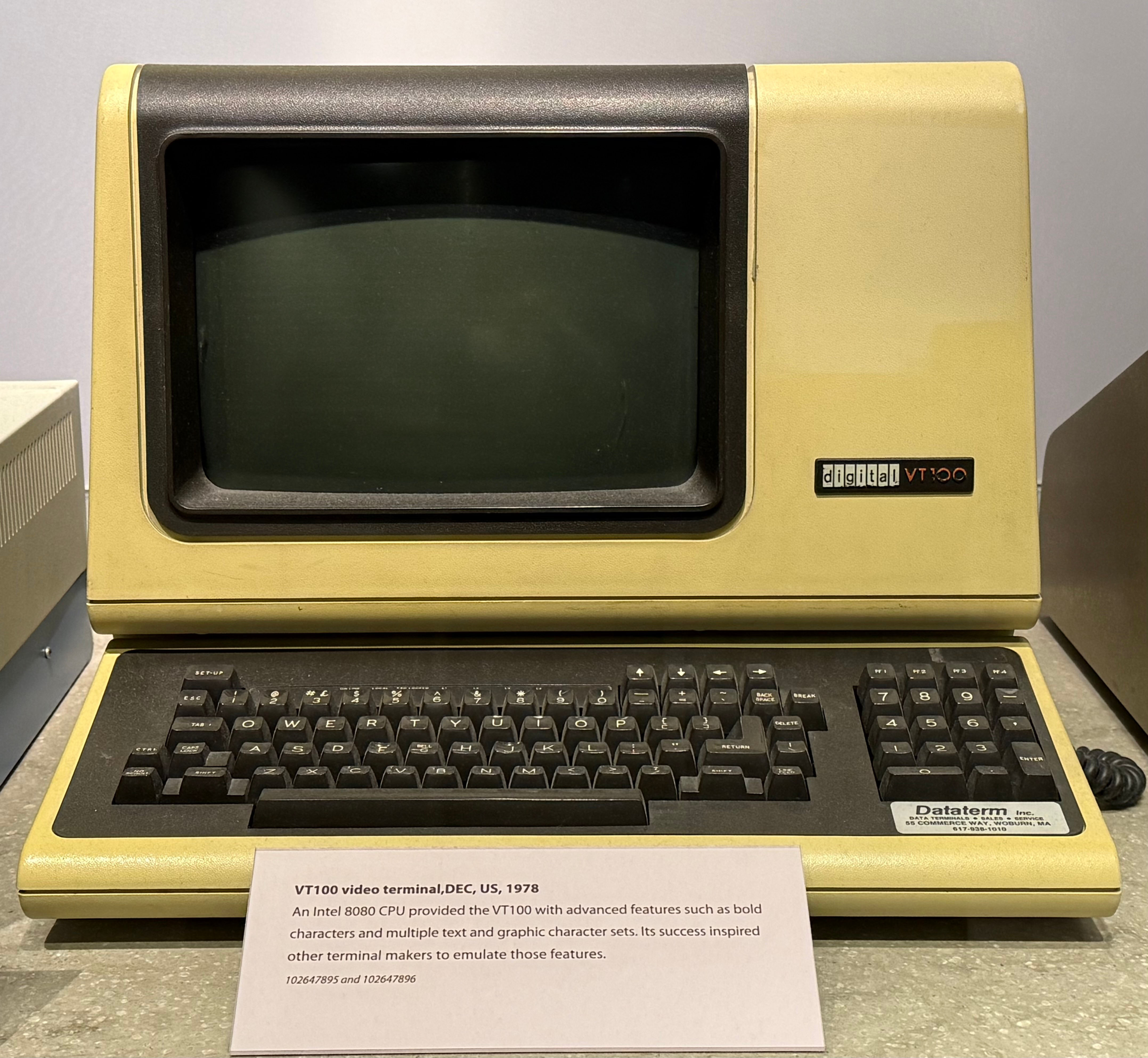
Typically, a computer must be able to read keyboard input and print characters on a screen in order to interact with the outside world. In the old days, these functionalities are handled by a terminal device which is separate from the main body of a computer.
Terminal and UART
This photo of the VT100 video terminal was taken at the Computer History Museum.

A serial bus connects the CPU with a device, such as VT100, and transfers data between the two. The most commonly used serial bus is likely the Universal Serial Bus (USB). USB is powerful but complex: there are at least 9 variants of USB connectors with various numbers of hardware pins, according to this Wikipedia page.
We start by introducing the much simpler UART serial bus which has only 2 hardware pins. UART stands for Universal Asynchronous Receiver/Transmitter and thus one hardware pin is used to receive bytes while the other is used to send (i.e., transmit) bytes.
When pressing a key on the keyboard, the terminal sends the corresponding character as a byte through the UART serial bus to the CPU and the operating system can read this byte through the Receiver hardware pin. When the operating system prints a character, it sends a byte through the Transmitter pin to the terminal. Asynchronous here means that electrical signals for keyboard input and screen output on the two pins are not related.
The code below shows how an operating system could use UART to control a terminal.
#define UART_BASE          0x10010000UL
#define SIFIVE_UART_TXDATA 0UL
#define SIFIVE_UART_RXDATA 4UL

void uart_getc(char* c) {
    int ch;
    while ((ch = REGW(UART_BASE, SIFIVE_UART_RXDATA)) & (1 << 31));
                 /* Read memory address 0x10010004 */
    *c = ch & 0xFF;
}

void uart_putc(char c) {
    while ((REGW(UART_BASE, SIFIVE_UART_TXDATA) & (1 << 31)));
            /* Read memory address 0x10010000 */
    REGW(UART_BASE, SIFIVE_UART_TXDATA) = c;
    /* Write memory address 0x10010000 */
}In short, the CPU provides two special memory addresses 0x10010000 and 0x10010004 for sending and receiving bytes through UART. When receiving a byte, uart_getc reads 4 bytes from 0x10010004 and the most significant bit indicates whether a byte is received. If the most significant bit is 1, the lowest byte is the byte read from UART (i.e., what is pressed on the terminal keyboard). When sending a byte, uart_putc first waits for the UART bus to become idle (i.e., UART has finished sending the previous byte) and then writes to address 0x10010000 with the byte to be printed on the terminal screen.
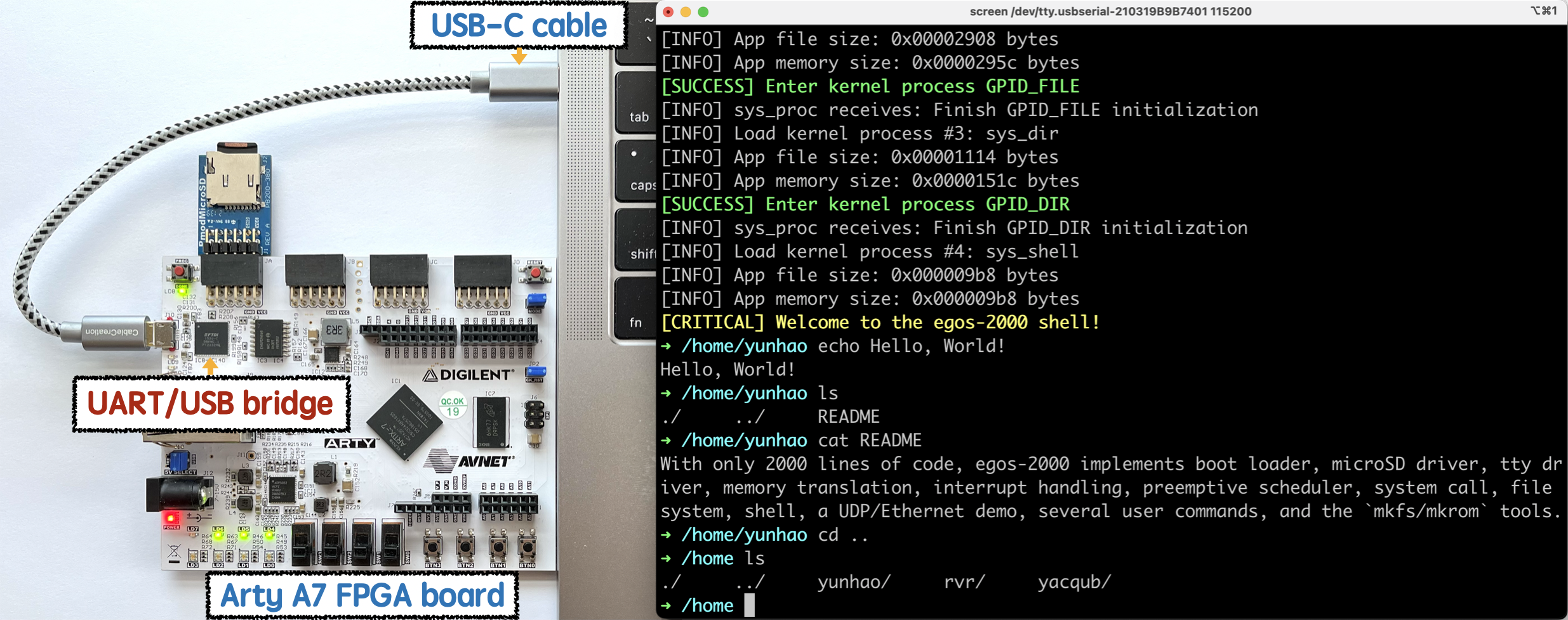
The code above looks very simple because most of the complexities have been hidden by the hardware. For example, when running egos-2000 on the Arty FPGA board and using a laptop (e.g., the screen command in MacOS) as the terminal, the UART/USB bridge black chip shown below will convert the electrical signals between UART and USB, so egos-2000 can use the simple UART serial bus and avoid the complexity of USB.

Still, the code above is a concrete example of memory-mapped I/O. Specifically, hardware manufacturers can define special memory regions that are used to control I/O devices, and different manufacturers can use different regions. Indeed, egos-2000 supports both QEMU and the Arty board which use different regions for the memory-mapped UART terminal. You can see such differences in earth/dev_tty.c: the macros with prefix SIFIVE and LITEX correspond to two different hardware manufacturers.
For Sifive, you can find the 0x10010000 address and the TXDATA/RXDATA offsets defined in Chapters 13.2 and 13.3 of their CPU reference manual, which is followed by QEMU.
SD card and SPI
In addition to a terminal, a computer typically needs a disk that stores blocks of data even when the computer is powered off. In this project, we use an SD card as the disk device and you will play with the SD card driver code in egos-2000.
An SD card is connected to the CPU through the Serial Peripheral Interface (SPI). SPI has 4 hardware pins, a bit more complex than UART. The picture below illustrates these hardware pins and the picture is from this Wikipedia page.

Specifically, consider the CPU as the "SPI Main" and the SD card device as the "SPI Sub". Each side has 4 hardware pins and their functionalities are described below.
- Chip Select (CS) is used to reset the SD card before using it.
- Serial Clock (SCLK) provides clock signals from the CPU (e.g., 20MHz).
- Main Out Sub In (MOSI) is used by the CPU to send bytes to the SD card.
- Main In Sub Out (MISO) is used by the SD card to send bytes to the CPU.
Similar to UART, the CPU provides memory-mapped I/O regions for communicating with the SD card through SPI. Different from UART, the SPI Main and SPI Sub exchange the bytes in their Shift Register during each communication. The code below explains how it works.
char spi_exchange(char byte) {
    uint rxdata;
    /* Send a byte through MOSI */
    while (REGW(SPI_BASE, SIFIVE_SPI_TXDATA) & (1 << 31));
    REGW(SPI_BASE, SIFIVE_SPI_TXDATA) = byte;
    /* Receive a byte through MISO */
    while ((rxdata = REGW(SPI_BASE, SIFIVE_SPI_RXDATA)) & (1 << 31));
    return (char)(rxdata & 0xFF);
}We omitted the macro definitions in the code for the memory-mapped I/O regions, and you can find them in egos-2000 or Chapter 16 of this CPU reference manual.
The first while loop is similar to the waiting logic in uart_putc. After sending a byte, the SPI bus immediately receives a byte from the SD card as the return value of spi_exchange. While spi_exchange uses the MOSI and MISO pins, the spi_set_clock function controls the clock signal sent out through the SCLK pin from the CPU.
void spi_set_clock(uint freq) {
    #define CPU_CLOCK_RATE 100000000 /* 100MHz */
    uint div                         = CPU_CLOCK_RATE / freq + 1;
    REGW(SPI_BASE, LITEX_SPI_CLKDIV) = div;
}As an exercise, read the sd_init function in earth/dev_disk.c in which you will see how spi_set_clock is used as well as some other initialization logic.
We have seen how to exchange a single byte between the CPU and the SD card. In the SD card standard, every SD card command has 6 bytes, so the operating system could ask the SD card to complete a particular task by sending the corresponding 6-byte command. Such commands form the basis of the SD card driver code in egos-2000.
Run an SD card command
Given a 6-byte command, the sd_exec_cmd function sends this command to the SD card and then waits for a reply with a timeout.
char sd_exec_cmd(char* cmd) {
    for (uint i = 0; i < 6; i++) spi_exchange(cmd[i]);

    #define TIME_OUT 8000
    for (uint reply, i = 0; i < TIME_OUT; i++)
        if ((reply = spi_exchange(0xFF)) != 0xFF) return reply;

    return 0xFF;
}With the sd_exec_cmd helper function, we can start to read some SD card driver code.
SD card driver
An SD card block is typically 512 bytes. When reading or writing an SD card, the operating system will read or write whole blocks. This is different from a terminal device which reads or writes in the granularity of bytes. Many operating systems thus distinguish block device and character device as two different device types.
Read an SD card block
The sd_read function reads a block from the SD card into memory address dst while the offset argument specifies which block to read. For example, if offset is 0, sd_read will read the starting block on the SD card.
static void sd_read(uint offset, char* dst) {
    /* Wait until SD card is not busy */
    while (spi_exchange(0xFF) != 0xFF);

    /* Send read request with cmd17 */
    char* arg = (void*)&offset;
    char cmd17[] = {0x51, arg[3], arg[2], arg[1], arg[0], 0xFF};
    if (sd_exec_cmd(cmd17) != 0) FATAL("CMD17 has non-zero reply");

    /* Wait for the data packet and ignore the 2-byte checksum */
    while (spi_exchange(0xFF) != 0xFE);
    for (uint i = 0; i < 512; i++) dst[i] = spi_exchange(0xFF);
    spi_exchange(0xFF);
    spi_exchange(0xFF);
}On the high level, the code above involves the following steps.
- Wait for the SD card device to become idle.
- Send command
cmd17to the SD card. Out of this command's 6 bytes, 4 bytes encode a block number (i.e.,offset) indicating which block to read. - Wait for the SD card to be ready to send back the 512 bytes of data.
- Receive 512 bytes from the SD card as the block data and 2 bytes as the checksum.
As an exercise, please also read the sd_write function in earth/dev_disk.c which writes a block of data into the SD card with a similar logic.
Multi-block read and write
You will implement an improved version of the SD card driver. The current driver uses SD card command 17 and 24 for reading and writing a single block, and the disk_read/write functions will use command 17 and 24 multiple times within a loop.
The SD card standard also provides command 18 and 25 for reading and writing multiple consecutive blocks. Your job is to replace the loops in disk_read and disk_write with your own SD card driver code using SD command 18 and 25. The details of command 18 and 25 can be found in this blog which contains some useful tables and figures. You can certainly find other online materials about these SD card commands.
After your code modifications, egos-2000 should be able to run normally on both QEMU and the Arty board since both of them provide an SD card device through the SPI bus. In addition, it could be very useful to write some unit tests for your driver code. For example, egos-2000 only uses the first 4MB of the SD card, and you can test your driver code with the rest of the SD card capacity. You could run your test code right after the disk_init() within earth/boot.c.
Accomplishments
You have learned about serial bus and memory-mapped I/O by reading through the device driver code in egos-2000. You have also written some driver code yourself for reading and writing SD card blocks which is the basis for the next project, file system.